Search
Propulsion

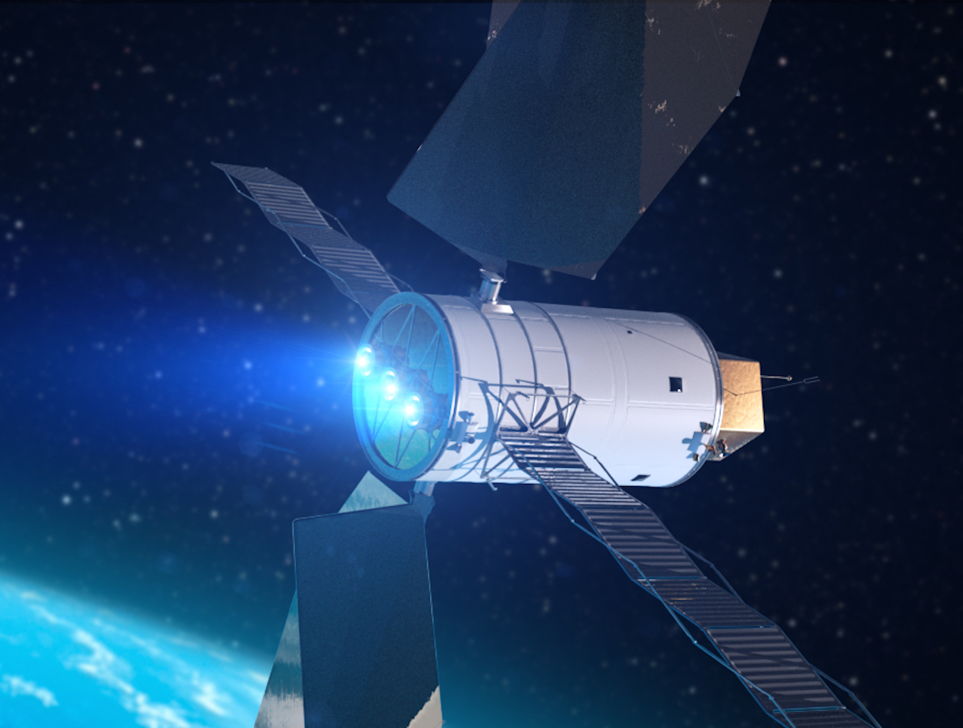
Small Spacecraft Electric Propulsion (SSEP) Technology Suite
Innovators at GRC have developed a suite of SSEP technologies for small, low-power spacecraft using Hall effect thrusters including a high propellant throughput small spacecraft electric propulsion thruster (LEW-TOPS-158), a power processing unit for SSEP (LEW-TOPS-157), an anode manifold plug for Hall effect thrusters (LEW-TOPS-159), and additional Hall effect technologies (LEW-TOPS-34). See the <i>Additional Information</i> section at the bottom of the page for more information on each technology suite component.
GRC is making these technologies available to U.S. companies through a no-cost*, non-exclusive license agreement and companion Space Act Agreement. Licensees may receive a comprehensive package of design and process documents including issued and pending patents, design drawings, materials specifications, and test data. Licensees will assist in defining system requirements and creating new platforms to use the SSEP technologies. This streamlined, collaborative commercialization strategy helps satisfy NASA exploration and science mission requirements while improving U.S. competitiveness in the global electric propulsion market and improving the success of new electric propulsion developments. Working alongside our licensees, GRC hopes to generate a compendium of SSEP knowledge as a living document, maintained by all users in a consortia-like environment.
*Although the license and Space Act Agreement are no cost to the licensees, licensees would be responsible for setting up and maintaining an EAR restricted file sharing space.
propulsion

Power Processing Unit (PPU) for Small Spacecraft Electric Propulsion
Key subsystems of a scalable PPU for low-power Hall effect electric propulsion have been developed and demonstrated at NASA GRC. The PPU conditions and supplies power to the thruster and propellant flow control (PFC) components. It operates from an input voltage of 24 to 34 VDC to be compatible with typical small spacecraft with 28 V unregulated power systems. The PPU provides fault protection to protect the PPU, thruster, PFC components, and spacecraft. It is scalable to accommodate various power and operational requirements of low-power Hall effect thrusters. An important subsystem of a PPU is the discharge supply, which processes up to 95% of the power in the PPU and must process high voltage to accelerate thrust generating plasma. Each discharge power module in this PPU design is capable of processing up to 500 W of power and output up to 400 VDC. A full-bridge topology operating at switching frequency 50 kHz is used with a lightweight foil transformer. Two or more modules can operate in parallel to scale up the discharge power as required. Output voltage and current regulation controls allow for any of the common thruster start-up modes (hard, soft or glow).
<br><br><br>
Propulsion

Improving Hybrid Electric Propulsion Efficiency
Electrically driven turbine engine compressor and propulsion fans require a large stability margin against stall conditions to avoid unwanted performance issues while undergoing transients in operating conditions. This stability margin, while it maintains safe operation, also necessarily reduces the engine performance. Despite extensive research efforts, no viable alternative methods for reducing the operable stability margin and improving engine performance exist. This current innovation, originally conceived for stall prevention, offers a solution by utilizing a supercapacitor in line with an electric motor and motor controller to rapidly change a compressor or propulsor fan speed. The use of the supercapacitor enables rapid extraction, or addition of power, to prevent the fan from stalling.
Additionally, this novel drive motor may be used for sensing stall event precursor signals by using the motor controller to detect variations in torque on the shaft caused by variance in loading on the blade system. The improved stall avoidance capabilities allow an engine fan to operate more efficiently, providing more thrust for a given frontal area, increasing operational range, reduced weight, and improved operational safety.
The related patent is now available to license. Please note that NASA does not manufacture products itself for commercial sale.
Propulsion
Anode Manifold Plug for Hall Effect Thrusters
Flow-restricting features in a Hall thruster anode manifold assembly, typically precision manufactured orifices, can contribute to significant flow non-uniformity if tolerances on the features are not properly controlled. Non-uniformity in flow distribution negatively impacts thruster performance. The anode assembly is usually a complex and expensive assembly to manufacture. Removing the flow restricting elements from the anode manifold structure in favor of modular insertable subcomponents (i.e., plugs) enables the use of more reliable and repeatable precision manufacturing techniques. The resulting components can be tested, characterized, and sorted for acceptance before being installed into the larger anode assembly (i.e., quality control can be performed at the subcomponent level). This may lead to increased performance and yield rate of the final assembly.
The flow restrictor plugs can be made in many different ways. The most basic flow restrictor takes the form of a precision hole machined into a cylinder, where the cylinder is then press fit into a hole drilled into the anode base. Alternate embodiments of the flow restrictor include precision machined nozzles, laminar flow elements, or sintered porous metal elements. The flow restrictor can also be made from a different material than the anode base, such as a precision ruby orifice contained in a metal carrier which is installed in a metal anode base. The plugs can be installed in a variety of ways, all of which create hermetic seals. Installation can include a press fit relying on plastic deformation or threading the plug component into the anode base. Welding on the top surface of the anode base can also be done to provide a robust hermetic seal.
propulsion

High Propellant Throughput Small Spacecraft Electric Propulsion Thruster
NASAs High Propellant Throughput Small Spacecraft Electric Propulsion thruster offers a propellant throughput capability of greater than 120 kg with a nominal thruster efficiency greater than 50%. The new thruster design combines heritage Hall thruster component design approaches with recent NASA GRC advancements in the areas of advanced magnetic circuit design, robust propellant manifolds, and center mounted cathodes. Prototypes of the High Propellant Throughput Small Spacecraft Electric Propulsion thruster have been fabricated and proof-of-concept has been demonstrated.
A significant advancement in the High Propellant Throughput Small Spacecraft Electric Propulsion thruster is NASA's optimized magnetically shielded (OMS) field topology. The new OMS configuration reduces discharge channel erosion rates compared to conventional Hall thrusters, while reducing front pole cover erosion rates compared to traditional magnetically shielded Hall thrusters. This system also includes a largely unibody structure to reduce fabrication cost, increase strength, and optimize thermal management. A coupling plate between the high voltage discharge channel and low voltage thruster body allows more efficient thruster assembly and verification processes. Other design advancements further simplify assembly, improve robustness, and optimize performance.
power generation and storage
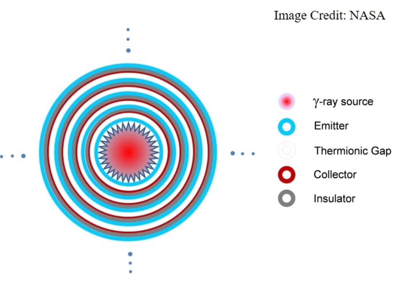
Multi-Layer Nuclear Thermionic Avalanche Cell
The Multi-Layer NTAC is comprised of a gamma-ray source and various layers of emitters, collectors, and insulators. Ideal emitter materials include elements with high atomic numbers, while ideal collector and insulator materials include elements with low atomic numbers. A high-energy gamma-ray (tens of keV to MeV) is used to liberate a large number of intra-band, inner-shell electrons from atoms within the emitter material for power generation through the primary interactions of photoelectric, Compton scattering, photonuclear, and electron/positron pair production processes. Secondary and tertiary electrons are liberated in the avalanche process as well. If a power conversion process effectively utilizes all liberated electrons in an avalanche mode through a power conversion circuit, the power output is drastically increased. Because power conversion is determined by the absorption rate of high energy photons, increasing power output requires either thicker collector material or a sufficient number of layer structures to capture the high energy photons, leaving no liberated electrons escaping (i.e., minimizing the leak of radioactive rays). The selection of materials, the thicknesses of the emitter, collector, and insulator, as well as the number of NTAC layers required are all determined by the energy of photon source. The thermal energy from radioactive decay can also be converted to electricity using a thermoelectric device to further increase power output. The Multi-Layer NTAC technology can be manufactured using existing semiconductor fabrication technology and can be tailored for small-to-large scale power needs, including kilowatt and megawatt applications.
power generation and storage
High Efficiency Megawatt Motor
The HEMM is a is a wound-field partially superconducting machine that implements a combination of rotor superconducting and stator normal conductor elements, along with an integrated acoustic cryocooler, to achieve some of the benefits of a superconducting motor without the need for an external cryogenic system. The combination of the described elements allows a motor to be built which essentially operates like any other motor when viewed as a black box, but substantially enhanced performance can be achieved. The incorporation of superconductors on the rotor to create a high-level magnetic field results in a specific power and efficiency that could not be achieved any other way. The HEMM can achieve over 98% efficiency in a lightweight electric machine with an operating power greater than 1.4 MW, a specific power greater than 16 kW/kg (ratio to electromagnetic mass), and a rated operating speed of 6800 RPM. The HEMM can be used as both a motor or a generator, offering a wide range of applications including propulsion systems for hybrid aircraft, electric trains, hybrid cars, and turboelectric ships, as well as generator systems for wind turbines, power plants, or motors for other industrial machinery.
Power Generation and Storage

Next Generation “Closed Strayton” Engine Design
The core “Strayton” generator technology consists of a gas turbine engine with short, axial pistons installed inside the hollow turbine shaft. These pistons form a Stirling engine that cycles via thermo-acoustic waves, transferring heat from the turbine blades to the compressor stage, which improves overall engine performance. Power to an alternator is, thus, delivered from both turbine shaft rotation and the oscillation of the internal pistons.
This synergistic relationship is markedly enhanced in a closed-cycle system, where the sealed turbine engine recirculates a working fluid heated via an external source, such as a hydrogen fuel cell and combustor. This system supports higher compression ratios, reduces the turbine diameter to less than 4”, and eliminates the need for large recuperators. Operational efficiency is projected to extend into the low temperature range (750° C), reducing the need for advanced materials and providing cleaner combustion for hydrogen-based applications. Pressurized, inert working fluids also replace mechanical bearings and gearboxes, enabling years of maintenance-free operation.
The fuel cell and Stirling cycle produce 10% of the total system energy, while the Brayton cycle produces 90%. Other external heat sources could include nuclear, solar, or biogas. Conservative estimates for the hydrogen fuel-cell configuration lifetime are in the 100,000 hour range.

